 ENGLISH
  DEUTSCH
  简体中文
简体中文  ESPAñOL
  한국어
한국어 
Automated Welding: Why Throughput Lives or Dies on What Feeds the Cell
Ask most people what automated welding looks like and they’ll describe the spectacle: a row of robots showering sparks over a car body as it glides down the line. This image is incomplete.
The welding robot is the most photogenic part of the process, but it is rarely the only part that determines how many cars leave the plant.
Because a welding robot has one hard requirement: the part has to be there, in the right pose, at the right moment.
Every second the cell waits on a part is a second of throughput gone.
This article looks at automated welding from the angle that actually decides line performance: the pipeline that feeds the cell. From the bin or rack where stamped parts arrive, through buffers and fixtures, to the precise “known position” where the welding operation takes over.
What Is Automated Welding?
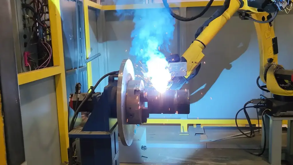
Automated welding is the use of robotic systems to perform welding operations with minimal human intervention. In automotive manufacturing, it dominates the body shop: doors, hoods, tailgates, fenders, floor pans, and roof bows are joined to the vehicle structure by welding robots working at line rate.
The business case is well established. Robots weld with repeatability no human can match over a shift, they don’t fatigue, and they take over work that is repetitive, physically demanding, and often hazardous.
With labor shortages tightening across manufacturing, the question for most plants is no longer whether to automate welding, but how to get the automated cell to run at its theoretical capacity.
And this is where the conversation usually goes wrong. Plants invest heavily in the welding cell itself. The robots, the guns, the controls. And then discover that the cell spends a meaningful share of its life waiting. The robot can only weld parts that arrive correctly presented.
The constraint isn’t the weld. It’s everything upstream of it.
The Hidden Half of Welding Automation: The Feeding Pipeline
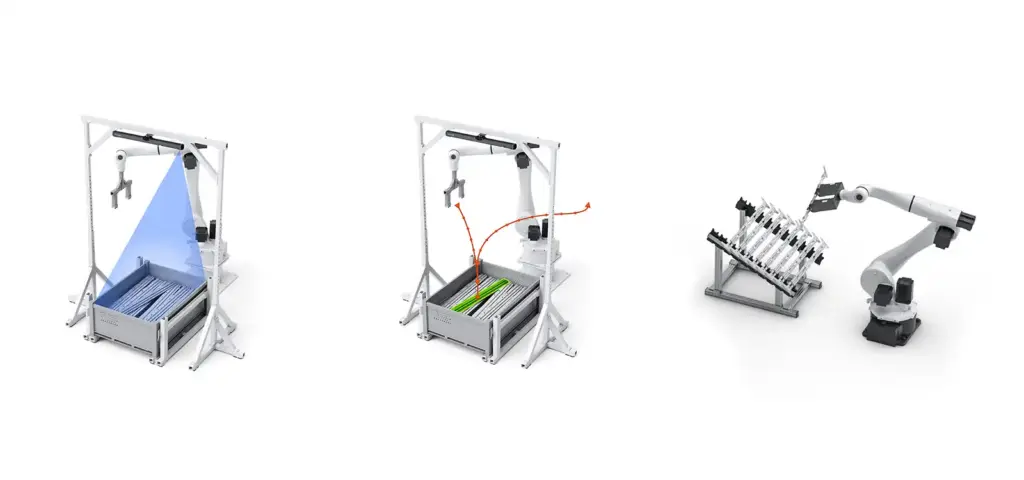
Before a door or a roof bow can be welded onto a chassis, it has to travel through a chain of well-orchestrated handling steps. In a typical automated body shop, that pipeline can look like this:
Bin or rack -> buffer -> fixture -> welding station
Each stage exists for a reason:
- The bin or rack is where parts arrive from stamping. Sometimes they’re hanging neatly on rack poles, other times piled in deep bins in random, chaotic poses. This is the only point in the pipeline where the part’s position is genuinely unknown.
- The buffer is a queueing station. A series of defined slots that decouples picking speed from welding speed. Think of it as a shock absorber of the line. If picking hiccups for a cycle, the weld station keeps drawing from the queue instead of stopping.
- The fixture holds one or several parts in a precise relative position, so the welding operation always sees the same geometry. In multi-part sub-assemblies, the fixture is where the parts come together before the weld.
Insight: only the first stage requires vision. Once a part has been placed into a buffer slot in a defined orientation, everything downstream is programmed robot motion between known positions. The hard problem? The one that historically kept humans standing at bins is getting a randomly-posed part out of a chaotic container and into that first known position, reliably, every cycle.
That problem is the domain of vision-guided robotic picking called pick-to-weld.
What Goes Wrong Upstream. And What It Costs
When automated welding lines underperform, the root cause is usually found in the feeding pipeline, not the weld itself. There are three main failure points.
1. Starved cells
If the picking operation can’t keep pace – or stalls entirely – the buffer drains. The welding station stops. In a plant running near lights-out, with automated forklifts and very few operators on the floor, there is nobody standing by to hand-feed the cell. Every stall becomes an operator call. And every operator call is measured in minutes of lost line time.
2. Mis-presented parts
Welding is only as good as the part presentation that precedes it. A part placed into the fixture slightly off-pose means a weld that lands off-target. This usually means rework, scrap, or a quality escape. Thin sheet-metal parts make this worse: they flex, they shift during transport, and they’re unforgiving of imprecise handling.
3. The container problem
This is the failure mode almost nobody budgets for: the bins themselves. Industrial bins take a beating. Forklifts push walls out of shape; years of use cave them in. Field measurements have found that roughly 85% of bins on real factory floors are damaged beyond their CAD specifications.
A vision system that navigates based on the bin’s original drawing is navigating a container that no longer exists. The result is collisions, aborted picks, and bins that can’t be emptied to the last part.
And the last parts matter. A bin abandoned with three parts still in it means another operator call, another interruption, another dent in overall equipment effectiveness. Multiply that across dozens of cells and hundreds of bins per shift, and “almost empty” becomes sort of expensive.
How 3D Vision Keeps the Cell Fed
Modern 3D vision solves the feeding problem by doing three things well: localizing the part, localizing the container, and delivering the part to a known pose. Here’s how each works in practice.
Localize the part. Any part, any surface
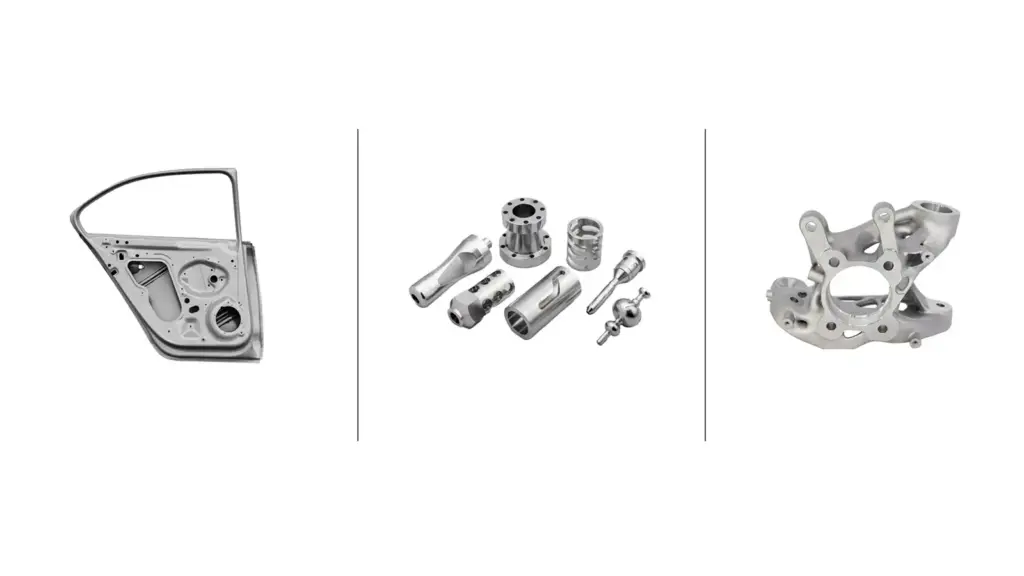
The vision system captures a dense 3D point cloud of the bin’s contents and matches it against the part’s CAD model to determine each part’s exact pose. Smart picking logic works top-to-bottom through the pile, handling occlusion so the right part is found first even in a jumble.
This has to work across the full range of automotive parts: large body panels over a meter long, but also the thin, awkward U-, L-, and Z-shaped brackets. Complex geometries create scanning blind spots from a single viewpoint, so multiview setups, two scanners looking into the scene from different angles, eliminate the gaps.
Surface finish is the other classic killer. Reflective aluminum and mirror-finish stamped steel blind ordinary sensors. Latest-generation scanner optics return clean, complete point clouds even on the shiniest parts, keeping localization solid where reflections would otherwise defeat the system.
Localize the bin. The real one, not the drawing
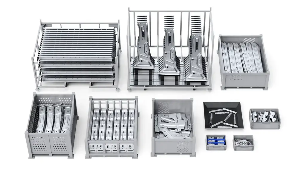
While the vision system relies on the bin’s CAD model, it can adjust based on the scanned reality of the container. Bins take damage: walls get dented, floors bow, a bin lands slightly off its nominal position. So rather than trust the model blindly, the system scans the actual bin and compares it against the CAD. When the sensor detects damage or deviation, the vision system recognizes it and recalculates a trajectory that avoids the real obstacle. Collision avoidance is planned against the bin’s scanned geometry, with the CAD model as the reference it measures against.
And when the standard picking strategy can’t reach a stubborn last part wedged against a wall, recovery logic takes over: engage the magnet, slide the part toward the center of the bin, re-localize, and pick it. That’s how bins get emptied to the last piece without a human ever walking over.
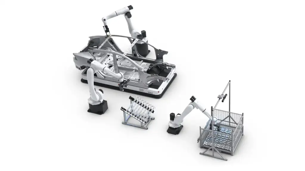
The vision system’s job ends with a precisely defined “known position” above the bin/rack. From that handoff point onward, every movement is deterministic. The transfer robot, the fixture loading, the presentation to the welding robots. All of it runs as programmed motion, because the vision system guarantees the starting pose.
This clean handoff is what makes the whole automated welding pipeline composable. Picking variability is absorbed at the bin; everything downstream just works.
A 50-Second Pick-to-Weld Cycle in Real Production
The proof that this architecture holds up isn’t a tradeshow demo. In US Tier-1 automotive production, a full pick-to-weld sequence – picking the part, placing it into the fixture, and completing the main-line weld – has been documented at 50 seconds, start to finish.
That number matters because it covers the entire unit sequence at production rate, on a real line, with real parts and real bins. It demonstrates that vision-guided feeding isn’t the bottleneck it’s often assumed to be. Done right, the picking stage keeps pace with the weld line and the buffer stays ahead of demand.
The Weld-Quality Knock-On Effect
There’s a second-order benefit that shows up in the quality numbers rather than the throughput numbers. Consistent placement means cleaner welds.
When the robot places every part the same way, every time – same pose, same contact points, same fixture seating – the welding operation sees identical geometry cycle after cycle. Weld parameters that were dialed in once stay valid. The result is fewer off-target welds, less rework, and less scrap. Precision upstream compounds into quality downstream.
ROI: What Automated Feeding Is Actually Worth
When evaluating the return on vision-guided part feeding for automated welding, the value stacks up across several lines.
Labor reallocation. No operators standing at bins performing repetitive, injury-prone picking. People move to higher-value work – and in plants that already can’t fill floor positions, that’s not a cost saving so much as a prerequisite for running at all.
Uptime. Real-bin detection and full bin emptying directly attack the two biggest sources of unplanned stops in the feeding pipeline: collisions with out-of-spec containers and abandoned last parts. Fewer operator calls, fewer line stops.
Quality. Repeatable placement reduces rework and scrap – costs that often hide in quality budgets rather than being attributed to the feeding system that caused them.
One-stop-shop leverage. One vision platform handles parts from under 2 cm to over 2 meters; picks from bins, racks, totes, and trays; and covers picking, loading, de-racking, and multi-part fixture feeding. The investment spreads across many stations and many part types, which is what compresses payback time.
Throughput protection. The hardest number to compute and the biggest one: the value of a weld line that never starves. If your line rate is worth thousands of dollars per hour, the feeding pipeline is not a peripheral – it’s the insurance policy on everything downstream.
Keep Your Weld Line Fed
It takes more than the welding cell to assemble a car. If your throughput targets depend on parts arriving correctly presented, cycle after cycle, the upstream pipeline deserves the same engineering attention as the weld itself.
Talk to Photoneo about vision-guided pick-to-weld – from chaotic bins and hanging racks to multi-part fixture feeding, one 3D vision platform trusted across 400+ installations worldwide keeps the cell fed and the line moving.


